Camshaft
Camshaft Design and Selection
Camshaft design and selection can be one of the most difficult and confusing aspects for an engine
designer. The most important aspect for a successful camshaft selection is that it is selected with
all of the components of the engine in mind. Aside from the camshaft configuration, there is the
non-trivial issue of the camshaft lobe design. There is a myriad of possibilities when it comes to
camshaft selection, and for good reason. Camshaft selection depends on the intended use of the engine,
and all the surrounding engine components. There is little use in installing a camshaft with high lift
and long duration if the cylinder heads are not up to the task, or the exhaust is going to choke the engine.
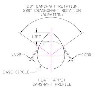
But what is lift and duration, anyway? Lift is the physical amount of movement the camshaft will lift the
valve off of its seat. Duration is the number of crankshaft degrees that the valve will remain off its seat
for. Refer to the diagram below to see where these dimensions come from.
So, as you can imagine, the further you lift the valve off the seat, the more room there is for air to
flow around the valve and into the cylinder, and the longer you hold that valve off the seat, the more time
the air has to flow into the cylinder. It sounds simple but it turns out that these values, along with the
cam timing and lobe separation have a significant impact on the engines operating range and power production.

As you can see in the attached image, the camshaft is simply an elongated shape that begins with a base circle. This
base circle is zero lift for the cam and valve. Once you move off this base circle, the cam acts to push on a lifter,
which converts the rotation to the straight line or linear motion required to open the valve. Maximum lift is achieved
as shown at the LIFT position, and this is where the camshaft lift is measured from. The duration is a bit more complicated.
There are two ways to measure duration. The first way, often labeled "advertised duration" is to take the angle or amount of rotation
beginning as soon as the cam profile leaves the base circle (and begins to lift the valve at all) and ends when the valve
is completely closed again. There are several problems with this approach. One is that there is a certain amount of clearance
in the valvetrain, such that the valve does not open at the exact instant that the cam profile begins to change. The second is
that the amount of flow through the valve at very low lifts is minimal, so minimal cylinder filling is occurring here. For
this reason, the more accurate value to compare is the "Duration at 0.050 in." often given by camshaft manufacturers.
This value is measured in an entirely different way. The camshaft is set up with a complete simulated (or actual) valve train,
including the lifter, rocker arm etc, and the duration is measured based on the moment the valve moves 0.050in. off the seat.
The amount of rotation is measured as shown in the diagram above. Actually, this diagram is a bit oversimplified, as the
amount of lift is actually measured after the multiplication through the rocker arm, but the principle is the same. Note that
the crankshaft duration is 2 times the value of the camshaft rotation. This is because of the ratio between the crankshaft
rotation and the camshaft rotation. The crankshaft rotates 2 times for every revolution of the camshaft and because the amount
of crankshaft rotation is what is really important to the engine operation, the duration is measured in degrees of crankshaft
rotation, not camshaft rotation. By measuring duration at 0.050" lift, direct comparison between different camshafts regardless
of valvetrain clearances or rocker arm multiplication is possible.

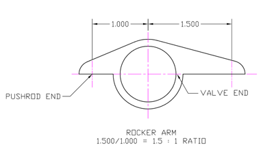
The rocker arm is a simple device used to convert the outward motion of the lifter and pushrod into inward motion to open the
valve. It is also typically used to multiply the camshaft profile anywhere from a 1:1 ratio all the way to a 2:1 ratio, or more.
Multiplying the actions of the camshaft allows for less movement of the lifter and pushrod, which helps to lower the linear momentum
in the valvetrain. A lifter and pushrod change direction approximately xxx times per second at 6000 rpm, so the less distance they
move, the easier they are to control. There is more discussion of the valvetrain and other configurations in the
valvetrain article.
In the most basic sense, the camshaft would open the intake valve(s) at the exact moment the piston begins its
downward motion to draw in a fresh intake charge, and close them as soon as the piston begins to move upward to
compress the charge. The exhaust valve(s) would have a similar motion, opening at the exact moment the piston
reached the bottom of its expansion cycle and closing at the exact moment the piston reaches the top of its
travel after expelling the exhaust gasses. There are several reasons it does not happen this way in a real
engine. First and foremost, the forces required to instantly open and close valves at an exact moment in
time are infinitely high and impractical to try and control. For this reason, valves are opened and closed
in a controlled manner as fast as possible without undue stress on the mechanical components. Second, it is
beneficial in terms of efficiency and performance to begin to open the intake valve sometime before the piston
reaches the top of its travel just prior to the inlet phase and close it sometime after it begins to move back
up during its compression stroke. Minor losses in intake charge while the exhaust valve (overlap) is still open
are more than compensated for by increased power and efficiency due to the longer amount of time the intake valve
is open.
The same holds at the bottom of the intake stroke, the extra time the intake valve is open allows the intake
charge (remember the discussion on momentum and cylinder filling) to continue to fill the cylinder even while
the piston is moving up. Since the intake momentum effect is minimal or non-existent at low engine speeds, a
camshaft designed to maximize intake valve duration (particularly the amount of time after the cylinder begins
to more upward before the valve closes) will result in reduced low rpm efficiency. This is because at low speeds,
the VE will be very low as some of the intake charge will actually be forced back out of the cylinder. This is
often described in an engine with a high rpm camshaft as when the engine “comes on the cam”. This is the moment
where the intake momentum becomes high enough to fill the cylinder effectively and generally results in the engine
going from a rough lumpy operation to a smooth operation with significantly more power.
We focused on the intake valve cycle here, but the exhaust valve opening and closing events have a significant
role in power production and operating range as well. The amount of time the intake valve and exhaust valve are
opened simultaneously is referred to as valve overlap. The higher the number, the more intake charge will be
bled off, particularly at low rpm, but at higher engine speeds, more air will flow through the cylinder unrestricted.
Here is an example. Imagine you have a tube with a hole in each end. Now imagine that both ends are open, and you
connect a hose to one end. The water flows out of the open end with little disruption as you put water into the inlet
end. You then close the outlet and finish filling the tube. Now imagine instead you close the outlet (exhaust)
side just prior to turning on the hose. Turn on the hose, let the tube (cylinder) fill with water, and then turn
off the hose. Now open the outlet side again. Which one will result in improved water flow through the tube?
You have lost more water in the process if both inlet and outlet are open simultaneously, but your water flow is
much smoother and less disrupted. The same principle holds true for intake and exhaust valve overlap. Overlap also
allows for some “flushing” of the cylinder to help expel any remaining burnt (and unburnt) gasses to allow the next
combustion cycle to have the freshest charge of air and fuel possible.
Lift is a much simpler topic. In general, increased lift will increase cylinder filling and engine performance up
to the limit of the cylinder heads. Of course, there are practical limits here as well, as the valve cannot come
into contact with the piston while opening or closing, and the further you open the valve the more force it will take
to close that valve. Excessive lift can put unnecessary stress on valve springs, rocker arms, and result in valve float.
A general rule of thumb is that if the cylinder head flows its maximum (or very close to it) at a given lift value,
there is little reason to open the valve much further than this amount. The amount of time the valve takes to open
and the amount of time the valve stays open (duration) typically has a bigger influence on engine operation. Keep in
mind, though, if you have installed some high flowing heads, you will not be taking advantage of them fully if your
camshaft selection does not open the valve sufficiently.
As always, more is not always better, and if the duration is too high or the overlap is too high for a given
engine intake, exhaust, and cylinder head design, the result will be an engine that is far from optimized.
It will be inefficient, will result in low power production, and have a very narrow operating range.